
New York City is the world’s most demanding high-rise laboratory. The city’s combination of compressed land area, extreme geological variability, dense urban wind tunnels, and one of the most aggressive building decarbonization mandates on Earth means that designing a skyscraper here requires solutions at the absolute frontier of structural and systems engineering. NYC Local Law 97, which mandates carbon intensity reductions of up to 80% by 2050 with hard financial penalties, means that sustainability is no longer a design add-on. It is a binding constraint, from the first line of structural analysis to the final MEP specification.

NYC skyline aerial at dusk
The city’s first skyscraper, The Tower Building, rose just 11 stories in Lower Manhattan in 1889. Today, 111 West 57th Street stretches 1,428 feet at a height-to-width slenderness ratio of approximately 1:24, one of the most structurally audacious towers ever built. The engineering distance between these two buildings represents a complete reconceptualization of how structures interact with gravity, wind, geology, fire, and energy.
The Engineering Physics of Height
Before any design decision is made, engineers must understand that a skyscraper is not a static object. It flexes, sways, settles, and breathes. The physics of structural behavior does not scale linearly with height, it compounds, and the compounding accelerates with every additional story.
Gravity loads, dead loads from the building’s own weight and live loads from occupants and equipment are the baseline design requirement. For buildings above approximately 300 feet, however, lateral loads become the governing design criteria. In supertall buildings, lateral forces can generate base overturning moments that exceed vertical gravity loads by a factor of three or more.
The P-delta effect compounds the problem: as a tall building deflects laterally under wind or seismic load, the eccentric position of gravity loads above the deflected point creates additional bending moments, a secondary structural effect that becomes progressively significant above 40 stories.
Vortex shedding adds a further layer of complexity. Wind passing a building’s corners creates alternating low-pressure zones that induce cyclic lateral forces perpendicular to the wind direction. If these vortices shed at a frequency that matches the building’s natural sway frequency, resonance occurs, potentially driving accelerations far beyond occupant comfort thresholds at wind speeds well below structural limits.
Site Analysis and Subsurface Investigation
Manhattan’s Geological Advantage — And Its Exceptions
New York City’s capacity to build so tall owes a great deal to its geology. The Fordham Gneiss and Manhattan Schist, extremely hard metamorphic bedrock formations that lie unusually close to the surface beneath Midtown (as shallow as 20 feet below grade) and the Financial District. This allows structural engineers to found deep caissons directly on rock, achieving bearing capacities among the highest of any major urban environment in the world.
However, this geological advantage is inconsistent. The bedrock beneath areas like Chelsea and the Garment District dips dramatically plunging to 60–100+ feet below grade before rising again in Lower Manhattan. Foundation depth and cost can therefore vary enormously within a few city blocks, making detailed subsurface investigation non-negotiable before structural system selection.
The Modern Site Investigation Protocol
A rigorous pre-design geotechnical program includes:
- SPT borings at minimum intervals down to bedrock, with rock core sampling for RQD assessment of bearing capacity
- Inclinometer monitoring programs for adjacent structures, informing both deep excavation design and contractual risk allocation
- Groundwater table investigation to develop the dewatering strategy during caisson construction
- 3D LiDAR scanning of the surrounding urban context capturing existing building foundations, utility networks, and adjacent structure geometries with millimeter precision
LiDAR-derived point cloud data, when imported into a BIM environment, provides a photorealistic, millimeter-accurate digital twin of the site context. Foundation engineers can model pile placement against real utility and adjacent foundation geometry rather than relying on potentially outdated municipal infrastructure drawings.
Our Point Cloud to BIM services transform LiDAR scans into fully coordinated, construction-ready digital twins — eliminating foundation risk before a single pile is driven.
Explore Point Cloud to BIM ServicesStructural System Design for Supertall Buildings
Side-by-side schematic of Steel Moment Frame / Concrete Core / Composite System
The structural system selection for a high-rise is arguably the single most consequential design decision in the project. It dictates cost, constructability, MEP coordination strategy, and how the building behaves under extreme loading events that may occur decades after completion.
Steel Frame vs. Concrete Core vs. Composite Systems
Steel moment frame construction dominated NYC’s early supertall era. The Empire State Building, Chrysler Building, and 30 Rockefeller Plaza all rely on steel frames that distribute lateral loads through rigid beam-to-column connections.
Reinforced concrete core-and-podium systems offer superior compressive performance and inherent mass damping. 432 Park Avenue: a 30×30-foot hollow concrete tube rising 1,396 feet with no interior columns, a structural concept of radical simplicity made necessary by its extreme 1:15 slenderness ratio.
Composite structural systems, combining a concrete core with steel outrigger trusses and perimeter mega-columns, represent the current state of the art. One World Trade Center uses a composite system in which the concrete core transfers loads to perimeter mega-columns through outrigger trusses at multiple mechanical floor levels.
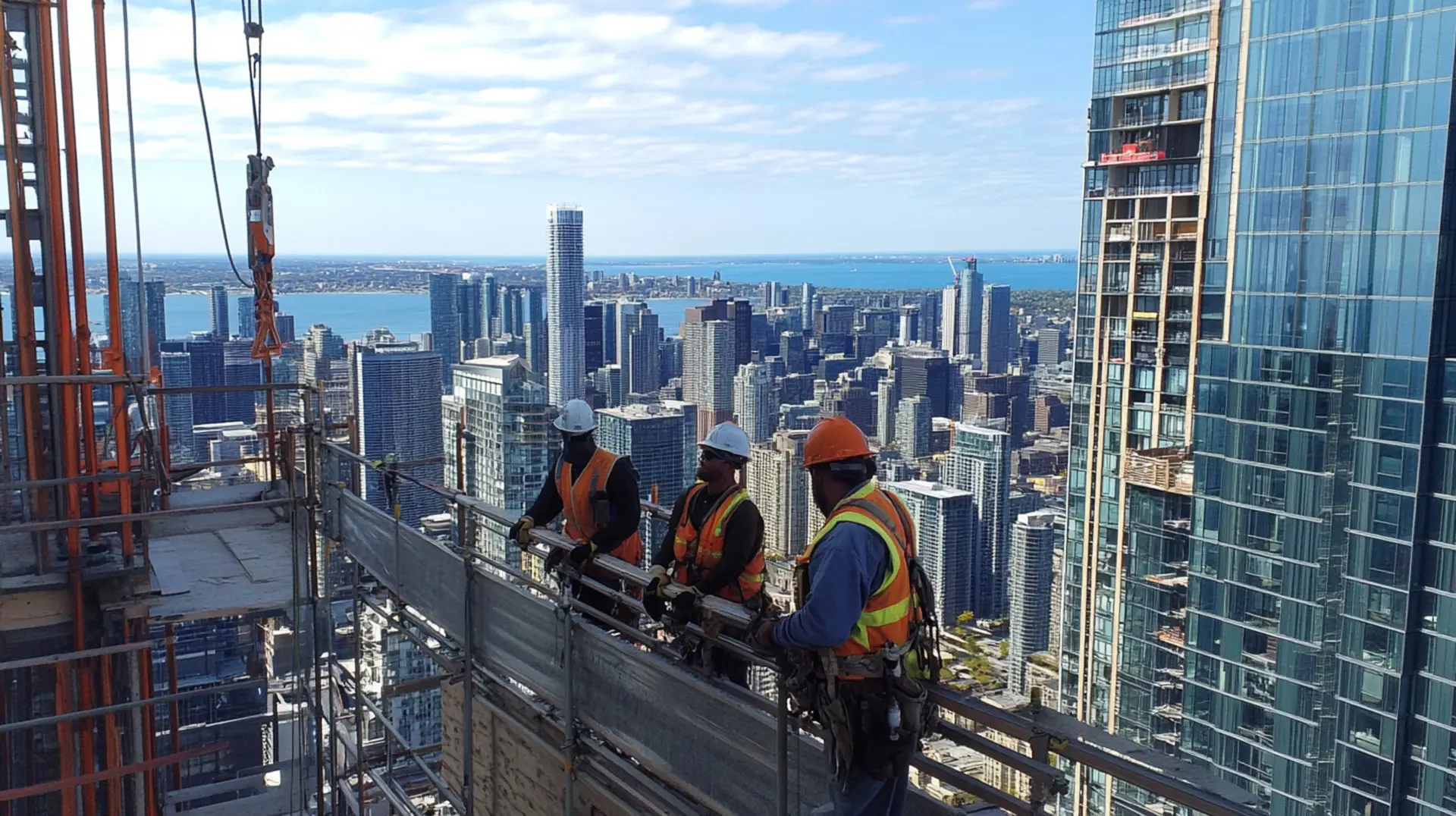
Structural steel frame mid-construction on a NYC supertall
The Slenderness Challenge
111 West 57th Street’s 1:24 slenderness ratio represents the current engineering frontier. ASCE 7-16 mandates maximum 10-year return period wind accelerations of 10–15 mg for residential occupancies. At extreme slenderness ratios, achieving these thresholds requires tuned mass dampers, careful aerodynamic massing, or both, structural comfort engineering becomes as important as structural strength engineering.
From LOD 350 structural models to finite element coordination, our BIM Modeling Services ensure your structural system is clash-free, code-compliant, and fabrication-ready.
Explore BIM ServicesWind Engineering — Designing against the Invisible Force
Wind Forces & Lateral Load Cross-Section
Wind is the governing structural design criterion for virtually every NYC supertall. Manhattan’s street grid creates a powerful channeling effect, amplifying wind speeds at upper floors exposed to unobstructed regional atmospheric flows. For any building above 40 stories, physical wind tunnel testing is not optional, it is the primary load determination method, mandated by both engineering practice and NYC Building Code.
Boundary Layer Wind Tunnel Testing
Physical wind tunnel testing uses scale models (typically 1:400 to 1:500) of the building and surrounding urban context in simulated atmospheric boundary layer flows. The ASCE Manual of Practice No. 67 and ASCE/SEI Standard 49-12 govern the conduct of these tests and the interpretation of results for tall building design.
Tests generate:
- Cladding pressure maps: peak positive and negative wind pressures on specific facade zones, used directly for curtain wall system design and anchor sizing
- Base shear and overturning moment envelopes: global structural loads for core and foundation design
- Floor-by-floor acceleration spectra: occupant comfort assessment under dynamic wind loading
- Pedestrian-level wind speed contours: ground-plane comfort and safety analysis

Architectural wind tunnel scale model test
Aerodynamic Optimization Strategies
- Chamfered corners (One World Trade Center): breaking the sharp 90-degree corner reduces base shear by an estimated 20% compared to an equivalent square-plan tower.
- Twisted floor plates: each floor rotates by a small angle, presenting a constantly changing silhouette to the wind and disrupting organized vortex formation.
- Tuned Mass Dampers (TMDs): 432 Park Avenue deploys two 800-tonne viscous fluid dampers at mechanical floors. The Citigroup Center (601 Lexington) had a 410-tonne TMD retrofitted post-construction in 1978 after a structural engineering error was identified.
Seismic Design in New York
New York is often perceived as seismically inactive — an assumption that is both incorrect and potentially dangerous. The city sits within ASCE 7-16 seismic design categories B/C, reflecting moderate seismic hazard from the Ramapo Fault System. A magnitude 5.0+ event could generate significant structural damage in Manhattan, particularly in pre-1970s steel frame buildings designed without modern ductility requirements.
Key seismic design strategies include:
- Special Moment-Resisting Frames (SMRF): steel connections detailed for high ductility, absorbing seismic energy through controlled yielding
- Concrete shear walls with boundary elements: designed to flex ductility rather than fail in shear — affecting post-earthquake reparability
- Viscous dampers: fluid-filled cylinders providing velocity-proportional damping effective for both wind and seismic loading simultaneously
- Seismic base isolation: lead-rubber bearing systems standard for NYC hospitals and emergency facilities where post-event operability is mandatory
Foundation Engineering — Building on Manhattan’s Bedrock
NYC foundations are among the most complex and costly in the world — not because Manhattan’s bedrock is inadequate (it is excellent), but because urban density requires excavation immediately adjacent to existing building foundations, active MTA transit tunnels, and a century of buried infrastructure.
Manhattan Schist bedrock
Rock Caisson Foundations
Rock caisson foundations, drilled shafts socketed into Manhattan Schist, are the standard approach. A typical supertall caisson is 8–10 feet in diameter, extending 20–40 feet below grade. End-bearing capacity on Manhattan Schist can exceed 150 tons per square foot, among the highest allowable bearing capacities in structural engineering practice globally.
One World Trade Center’s foundation involved 58 caissons extending up to 70 feet below grade, with caisson caps tied by a 72,000-ton reinforced concrete mat slab, one of the largest foundation systems in New York construction history.
Managing Adjacent Construction Risk
Managing adjacent construction requires:
- Structural underpinning of adjacent building foundations prior to any excavation commencing
- Real-time automated settlement monitoring using inclinometers, tiltmeters, and precision settlement sensors on adjacent structures
- Jet grouting or soil mixing programs to create ground improvement zones before excavation
- Integration of all real-time monitoring data into the project BIM environment as a live risk dashboard
MEP Coordination in High-Rise Buildings
In a supertall building, Mechanical, Electrical, and Plumbing systems are structural co-determinants. Rooftop chillers can weigh hundreds of tonnes. Hydraulic risers running the full building height require pressure-breaking zones every 25–30 floors. Without rigorous digital coordination, MEP systems compete with structural elements for ceiling void space — and resolving those conflicts by modifying structural elements is a structural safety risk, not merely a cost or schedule issue.
Why LOD 350+ BIM MEP Coordination Is Non-Negotiable
The benchmark for high-rise MEP BIM coordination is LOD 350–400, where every duct, pipe, conduit, and hanger is modeled with actual installation dimensions and required maintenance clearances. Automated clash detection using Navisworks or Revizto identifies all hard and soft clashes, typically running into the thousands on a supertall project, resolving them digitally before construction begins. Studies of BIM-coordinated high-rise MEP programs consistently report coordination time reductions of 35–40% and the effective elimination of on-site structural conflicts.

High-rise MEP mechanical room, ductwork and coordination
Our MEP BIM Services deliver LOD 400-coordinated models that prevent costly on-site structural modifications in high-rise projects.
Explore MEP BIM ServicesBuilding Envelope and Facade Performance
The building envelope of a NYC skyscraper must simultaneously resist wind-driven rain at cladding pressures exceeding 80 PSF, maintain thermal performance across NYC’s temperature range from -10°F to 95°F+, resist UV and environmental degradation over a 50–100 year design life, and comply with stringent energy performance requirements under Local Law 97.
Unitized curtain wall systems, factory-assembled floor-to-floor panels installed from inside the building, have become standard for NYC supertalls above approximately 30 stories. One World Trade Center’s unitized panels weighed up to 1,200 lbs each, requiring specialized tower crane rigging plans integrated with the structural erection sequence.
High-performance glazing, triple insulating glass units with low-e coatings and thermally broken framing, is now effectively mandated by NYC energy codes for new construction and directly impacts the Local Law 97 operational carbon compliance calculation.

Glass curtain wall unitized façade
Fire Safety and Life Safety Engineering
A fire emergency at floor 70 of a supertall building presents evacuation challenges with no precedent in low-rise design. Standard full-building simultaneous evacuation protocols become physically unworkable when total evacuation time can exceed two to three hours for all occupants. High-rise fire safety is a distinct engineering discipline.
Best-practice strategies include:
- Phased evacuation protocols: immediate evacuation of the fire floor and two floors directly above and below; all other occupants shelter in place or relocate to refuge floors
- Dedicated refuge floors every 25 stories: ADA-accessible holding areas with enhanced fire ratings and two-way communication with the fire command center
- Pressurized stairwells: positive air pressure maintained relative to adjacent floors, preventing smoke infiltration into primary evacuation routes
- 3-hour fire-rated structural enclosure: all steel elements require intumescent coating, gypsum encasement, or spray-applied fireproofing — all dimensions coordinated in BIM
Best Strategies to Improve Efficiency in Older NYC Skyscrapers
The question of improving energy efficiency in older NYC skyscrapers has become operationally urgent. Local Law 97 sets hard carbon intensity limits for buildings above 25,000 sq ft, with financial penalties of $268 per ton of CO2 equivalent above the limit, beginning in 2024 and escalating significantly through 2030. For many pre-1970s towers operating with legacy steam heating systems and single-pane aluminum curtain walls, compliance requires genuine capital investment.
As of the latest analysis, 92% of large NYC buildings met their 2024 emissions limits, but the 2030 thresholds impose a significantly lower emissions intensity cap that will require deeper investment from the remaining non-compliant stock.
A prioritized retrofit strategy:
- LED lighting and smart controls — 50–70% lighting energy reduction, 3–5 year payback periods. The highest-ROI retrofit available for most existing buildings
- BAS retro-commissioning — integrating siloed HVAC, lighting, and metering into a unified building automation platform. Can reduce total energy use by 15–25% with minimal capital expenditure
- Air barrier sealing — targeting infiltration at curtain wall joints, window perimeters, and service penetrations
- Window replacement — upgrading original single-pane aluminum curtain wall to high-performance double or triple IGU systems can reduce heating loads 30–40%
- Chiller plant upgrades — replacing inefficient older equipment with modern variable-speed magnetic bearing chillers can reduce cooling energy 30–50%
- Heating electrification — transitioning from steam or gas-fired boilers to heat pump systems is the single most impactful Local Law 97 compliance measure for gas-dependent buildings
Sustainability and NYC Local Law 97 Compliance
Local Law 97, enacted as part of NYC’s Climate Mobilization Act in 2019, is the most ambitious building decarbonization mandate of any city globally. For new high-rise construction in NYC, LL97 compliance is now a primary design driver from schematic design — not a retrofit applied at the end of the project.
Buildings are responsible for over two-thirds of NYC’s greenhouse gas emissions, and the city’s 2024 greenhouse gas inventory showed building emissions were nearly 27% lower than 2005 baseline levels — a sign that policies are working, though the pace must accelerate to meet 2030 targets.
Key sustainability strategies for new high-rise construction:
- Full electrification of all heating and domestic hot water systems, eliminating gas combustion — highest-impact measure under LL97’s carbon calculation methodology
- Ground source or air source heat pump systems replacing conventional steam or gas-fired boiler plant
- On-site or off-site renewable energy procurement via Power Purchase Agreements or Renewable Energy Credits
- Carbon-sequestering structural materials: supplementary cementitious materials (fly ash, GGBS) in concrete mixes; mass timber in appropriate applications
- LEED v4 or WELL v2 certification as an integrated design framework ensuring sustainability targets are embedded across architectural, structural, and MEP decisions
Summing Up!
Designing skyscrapers in New York City means engineering at the absolute limit of structural, geotechnical, and building systems capability, in an urban environment that allows no margin for error in adjacent construction, and under a regulatory environment where energy performance has become a hard compliance obligation with financial consequences.
The buildings that will define NYC’s next skyline generation will be characterized not just by their height, but by the intelligence of their engineering: structural systems that resist extreme forces without material excess; MEP networks coordinated digitally before a single bolt is tightened; envelopes that perform thermally, structurally, and architecturally across a 100-year design life; and sustainability strategies built in from the very first design decision.
That level of execution demands digital-first workflows, BIM, point cloud data integration, parametric structural modeling, and LOD 400 MEP coordination, not as aspirational future tools, but as the non-negotiable baseline standard of practice in every serious high-rise project today.
Frequently Asked Questions (FAQs)
How do engineers design tall buildings safely against wind?
Designing tall buildings safely against wind involves: boundary layer wind tunnel testing to determine actual wind pressures and occupant comfort accelerations; aerodynamic shape optimization (chamfered corners, twisted profiles, tapered massing) to reduce vortex shedding; Tuned Mass Dampers weighing 400–800 tonnes to absorb sway energy; and outrigger and belt truss structural systems to maximize lateral stiffness.
What obstacles do skyscrapers face as they get taller?
As buildings get taller, they face compounding obstacles: the P-delta effect amplifying lateral deflection; vortex shedding driving occupant discomfort below structural limits; MEP hydraulic pressure zoning requirements; fire evacuation time constraints; and foundation loads exceeding shallow bearing capacity. Designers address these through composite outrigger structural systems, TMDs, BIM-driven MEP coordination at LOD 350+, phased fire evacuation planning, and detailed geotechnical programs.
How deep are foundations for NYC skyscrapers?
In Midtown, where Manhattan Schist bedrock is relatively shallow (20–40 feet below grade), rock caissons can be founded at moderate depths. Where bedrock dips in Chelsea or parts of Lower Manhattan, caissons may extend 70–100+ feet. One World Trade Center's caissons reached 70 feet into bedrock. The critical criterion is adequate rock socket penetration, typically 3–5 feet into sound schist, to achieve the design bearing capacity reliably.
What role does BIM play in designing high-rise buildings?
BIM is the fundamental coordination and delivery platform for contemporary high-rise design. It enables: structural analysis model integration linking Revit or Tekla to FEA software; MEP clash detection at LOD 350–400 preventing on-site structural modifications; fabrication-ready shop drawing extraction with millimeter precision; real-time foundation monitoring data integration during construction; and energy performance modeling for Local Law 97 compliance and annual reporting.
What is a Tuned Mass Damper and which NYC skyscrapers use them?
A Tuned Mass Damper (TMD) is a massive weight, typically 400–800 tonnes, suspended near the top of a supertall building, tuned to the building's natural sway frequency. When the tower deflects right, the mass swings left, exerting a counterforce that reduces motion amplitude and acceleration. 432 Park Avenue uses two 800-tonne viscous fluid dampers. 601 Lexington (Citigroup Center) had a 410-tonne TMD retrofitted post-construction in 1978 as a critical safety measure.
How can older NYC skyscrapers improve energy efficiency?
Older NYC skyscrapers should follow a disciplined retrofit sequence: LED lighting and smart controls first; BAS retro-commissioning second; air barrier sealing and window replacement third; chiller plant upgrades fourth; and heating electrification as the capstone measure for Local Law 97 compliance. For buildings facing LL97 penalties, a formal compliance pathway analysis, modeling retrofit combinations against the 2024, 2030, and 2050 thresholds, should precede every capital investment decision.


