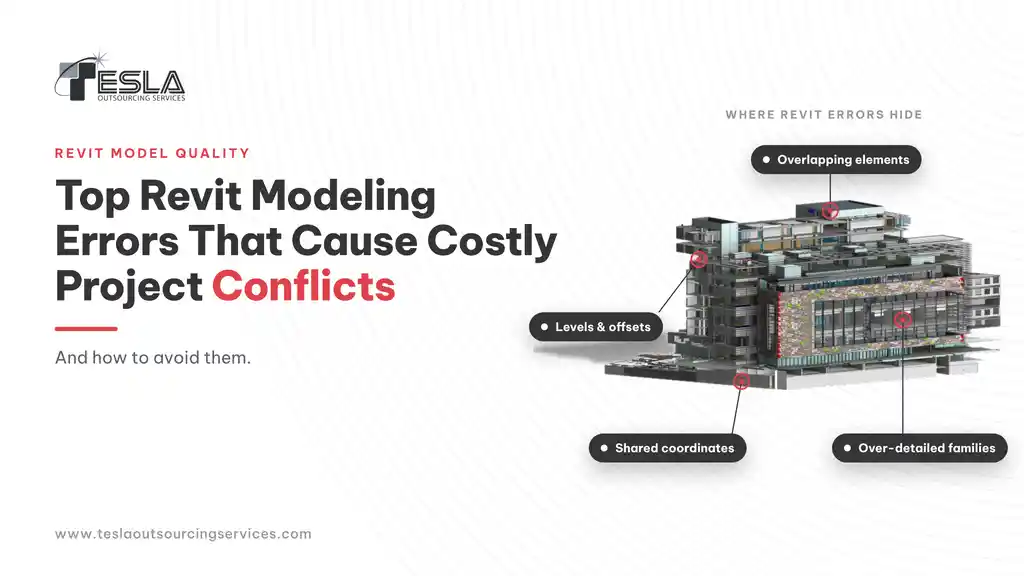
Does your Revit model look right to you? This is a very important question. Even though you have created all the components to represent your construction project in Revit, there can still be errors in the data created by the model. These errors can be simple mistakes that may appear to be nothing serious, but can turn into major problems once the model is put to use for project coordination, quantity take-off, production information and on-site construction. Each of these stages can uncover errors in the model data.
While many errors within Revit modeling could be remedied with more time, many errors are caused by poor setup, inconsistent standards, missed warnings, and insufficient quality checking, to name a few of the most common errors found. This article covers five of the most common Revit modeling errors and methods for finding them before they become an RFI, change order, coordination problem, or even inaccurate project data.
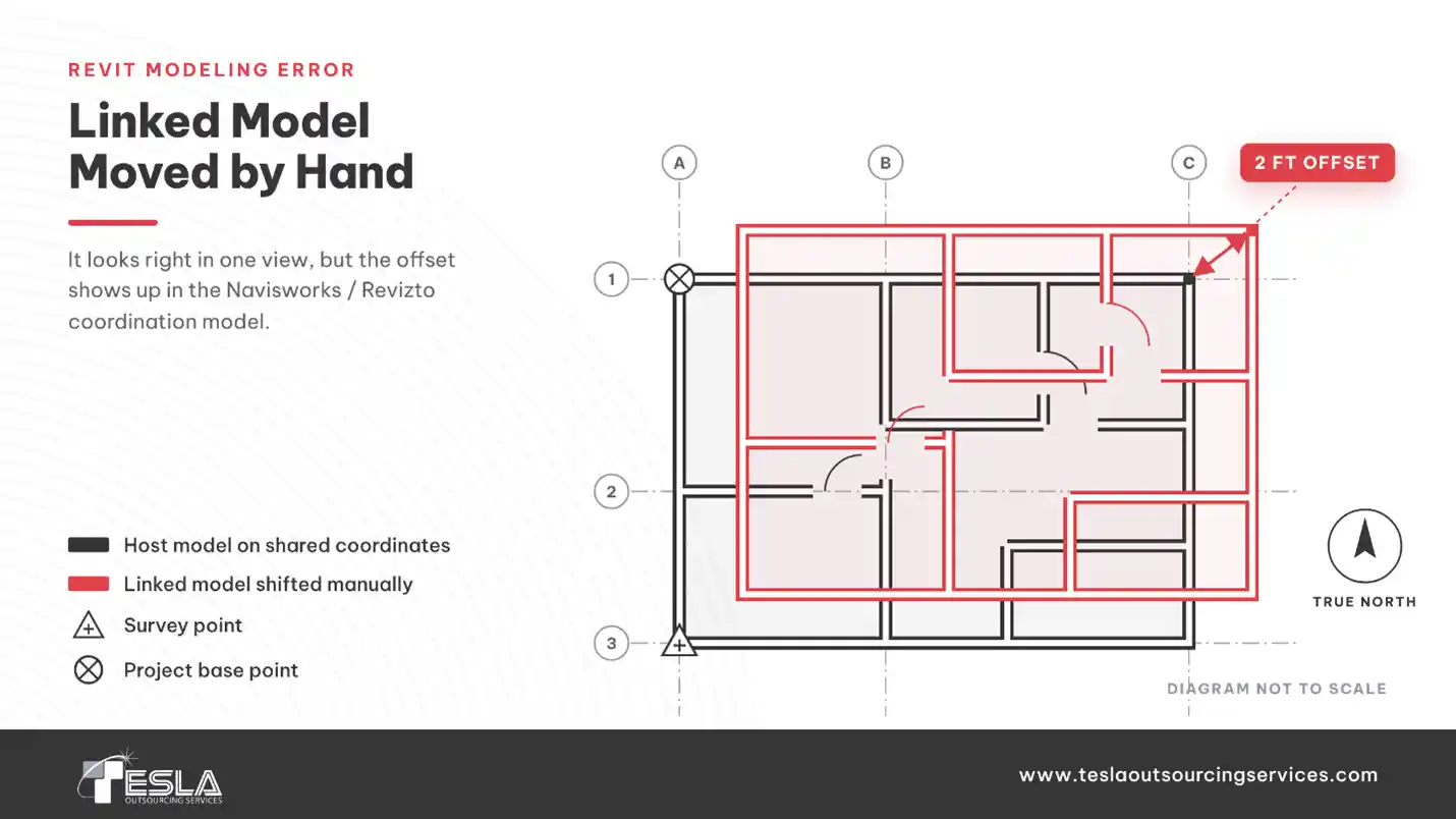
Revit modeling error: a linked model moved by hand sits 2 ft off the shared coordinates.
Modeling Without the Correct Coordinates
Error
This series of potential Revit errors begins with perhaps the largest error possible for building models – establishing a model that is not created in correct coordinates. This happens when project teams begin their work before they establish survey information for a project (the survey point), project base point, true north, and shared coordinates for the models. After that, linked models are moved around by hand in order to make them look “right” in certain views.
Why is this a problem?
Manually adjusting linked models can actually mask a problem with coordinates. It is not until models are opened up in tools such as Navisworks or Revizto as part of a site-wide coordination that the problem is uncovered, only to cause large amounts of rework across all disciplines.
Solution
Coordinate errors can occur before the design is even started. Setting up the Revit model at the start of a project with the correct survey point, project base point, true north and shared coordinates for linked models is essential to avoid errors such as a manually shifted linked model that has been apparently placed in the correct position, only to cause unexpectedly displaced items in the Navisworks / Revizto project coordination model.
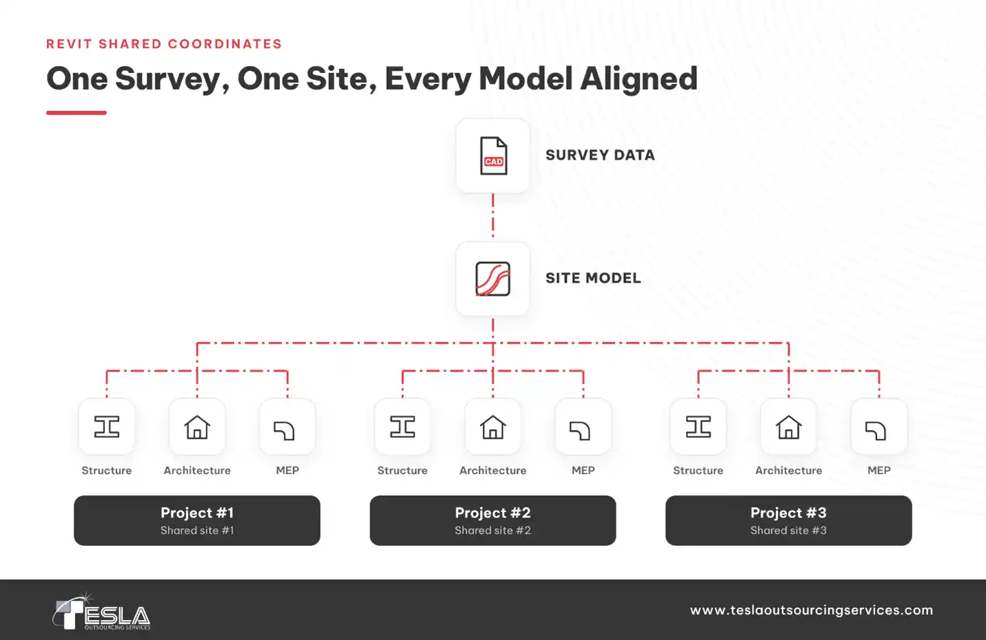
Revit shared coordinates: one survey and one site model keep every linked project model aligned. Graphic: Tesla Outsourcing Services.
Using Incorrect Levels, Offsets, and Constraints
Error
Elements are being hosted on incorrect levels with unknown offsets, in order to unintentionally connect to other elements (such as a wall ending at a column, etc.). Some elements are completely unconnected and therefore left to be ‘finished off’ later by others.
Why is this a problem?
These types of errors will not change with a level change and can result in many problems, including gaps, duplicated elements, incorrect elevations, and co-ordination errors that are discovered late in the project.
Solution
Model against approved levels, and use meaningful base and top constraints. Intentional offsets should be reviewed through schedules or automated checks against model information. In investigating large or unusual offsets, make sure that modeler information is provided to support the offsets, and reviewer information is provided to question the offsets.
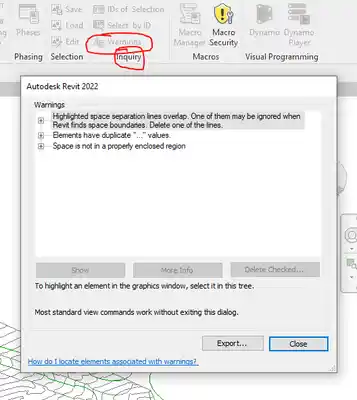
Revit Warnings @ https://forums.autodesk.com/t5/image/serverpage/image-id/1183545i72353ABFD61D26E8/image-dimensions/2000?v=v2&px=-1
Ignoring Revit Warnings
Error
The errors associated with unaddressed Revit model warnings are very common. They often indicate that there are simple issues with a model, some of which could have serious consequences if left unfixed.
Why is this a problem?
Not every warning is critical. However, a growing number of warnings can make it difficult to distinguish between important issues and minor flaws. In particular, duplicate elements can affect quantities, overlapping elements can cause problems with connections, and elements that are only slightly off axis can cause problems with alignment during construction and afterwards.
Solution
Review warnings regularly (not only before submittal) and assign severity to them. It is best to create a warning log to track all model audits and follow up on them. High-risk warnings should be fixed immediately. Accepted exceptions should be documented.
Creating Duplicate or Overlapping Elements
Error
It is caused when walls, floors, ceilings, ducts, pipes, etc. are duplicated at the same location. This is commonly caused by group editing, copy-monitor workflows, design options, etc. being imported into the model again and again.
Why is this a problem?
Duplicates can produce incorrect quantities, confusing clash results, graphical flickering, hosted-element failures, and double-counting in schedules or cost plans.
Solution
Use selection filters, schedules, interference checks and warning reviews to find out about duplicates. Verify the destination location before placing a copied object. Remember that copying and pasting objects across a model or across models does not constitute ‘controlled’ use of linked models or ‘approved’ transfer of content between models.
Using Poorly Built or Over-Detailed Families
Error
Families containing too much geometry (all plan & section views, backgrounds, detail regions, imported CAD models, nested families, too many parameters, etc.), incorrectly dimensioned & connected components (e.g. incorrectly set-out clearance zones and dimensions of products).
Why is this a problem?
This can lead to several problems. Firstly, a heavy family repeated hundreds of times can lead to poor model performance. Secondly, incorrect MEP connectors can mean that the system calculations are wrong. Finally, items such as clearance zones and product dimensions must be accurately modeled to avoid real installation problems.
Solution
Keep families as simple as the deliverable actually requires. Model only the geometry needed for coordination, quantities, and clash detection. Set clear family authoring standards (LOD/LOI targets, parameter limits, polygon counts) before content is built, and audit families before they go into the shared model. Use view-specific display (symbolic lines, detail level visibility) instead of modeling fine detail in 3D. Test heavy families in a lightweight model first to catch performance and connector issues early, rather than discovering them after hundreds of instances are placed.
Confusing Model Geometry with 2D Representation
Error
Modelers hide incomplete or incorrect 3D work using detail lines, filled regions, masking regions, or view-specific components.
Reason
The issue will likely become apparent when another party uses the incomplete work to continue development. This work can quickly unravel when you try to review, quantify, or section up the work done by another team member.
Solution
Avoid using 2D drawings to hide errors in the model’s 3D geometry. Verifying key conditions in plans, sections, elevations, and 3D views can help catch errors before others use the faulty information to continue their work. Ensure that all items represented in the model are represented correctly to fulfill the purpose of the model’s creation.
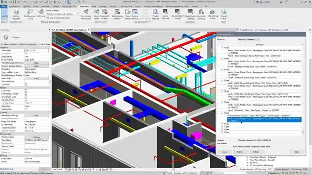
Revit MEP coordination
Breaking MEP Connectivity
Error
Ducts, pipes, cable trays, equipment, etc. appear to connect but, in fact, are not. This includes errors with connector sizes, flow direction, system classification, and level.
Why is this a problem?
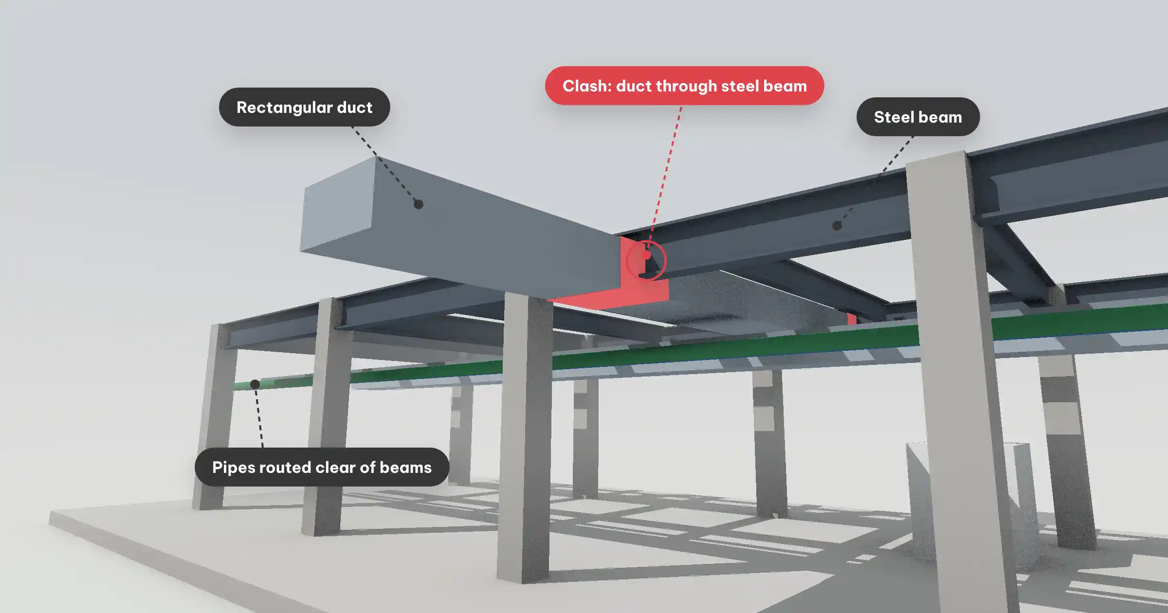
Disconnected networks can compromise system calculations, create issues for schedules and other fabrication-related outputs, and create problems for clash checks, resulting in a single error in a connection, such as a small gap at a fitting, being able to cause problems for an entire system.
Solution
Prevent this error by using MEP system inspection tools such as the MEP Connector Check (which checks connector size for proper fitting selection) to identify unassigned and disconnected MEP components and related issues that need to be coordinated and scheduled and then tested along a representative route between source and terminal ends to verify the proper slope, elevation, size, system and related information.
Mismanaging Worksets, Links, and Ownership
Error
Elements are placed on incorrect worksets, links are loaded from inconsistent locations, or users make entire worksets editable without a clear need.
Why is this a problem?
This creates visibility problems, ownership bottlenecks, longer opening times, accidental unloading and work to re-coordinate based on out-of-date versions.
Solution
Worksharing and links are organized to enable collaboration and loading of only relevant parts of the model. Responsibility for links is assigned. Loading of the latest versions from the cloud or shared path is performed on a regular basis. Synchronization with the central model is performed with clear comments on changes made.
Communication failures between trades – the same disconnect that causes a duct and a beam to “appear” connected in one model but not the field – are responsible for roughly 17% of all rework causes. Shared 3D models reduce this, researchers note, but rarely eliminate it.
Inconsistent Naming and Parameter Data
Error
Families, types, systems, views, sheets, rooms, spaces, and parameters are named differently by each modeler. Required fields are blank, duplicated, or populated as free text.
Why is this a problem?
Because information that has not been structured properly in the model cannot be dealt with by subsequent processes and therefore has to be corrected by hand in detail (LOD 500 is just as expensive as geometry errors).
Solution
Use approved naming rules for Families, Types, Systems, Views, Sheets, etc. Ensure all models use shared parameters with controlled values. Use data dictionaries for all information stored in the model’s shared parameters. Verify that schedules have been created correctly using conditional formatting to highlight any missing information.
Submitting Without a Model Health and Coordination Check
Error
A completed model is published because it looks complete on a few views, without checking for model warnings, file size, links, worksets, CAD data, rooms, coordinates, etc., and clashes with other models.
Why is this a problem?
Downstream teams will then be coordinating against information that is incomplete and possibly unstable. The errors will be propagated to drawings, quantities, issue registers, fabricated models, and on-site decisions – getting more expensive as time goes on.
Tools to track
Introduce formal Stage Gates to the model development stages – modeler self-check, discipline QA check, and Coordination approval. Develop a simple, repeatable checklist in schedules using Revit Schedules, record results against the stage gate in the Project Schedule and use tools such as Dynamo, pyRevit, or model-checking platforms to automate audits against the agreed checklist. The same stage-gate discipline is one of the first things to test when you bring in an external team. Our guide to BIM outsourcing strategy and vetting partners explains how to check a partner’s QA/QC process before you hand over a model.
A Practical Pre-Publish QA Checklist
- Confirm coordinates, levels, grids, orientation, and linked-model positions.
- Review critical warnings, duplicates, unconnected elements, and unusual offsets.
- Worksets – can the model be published to the correct worksets for issue review?
- Validate family geometry, MEP connectors, clearances, and classification.
- Audit naming, required parameters, room/space data, and asset information.
- Compare interdisciplinary clashes and mark off all issues that have been solved in the model.
- Sheets, Views, Schedules & Exports – confirmed to be using the correct revision and status.
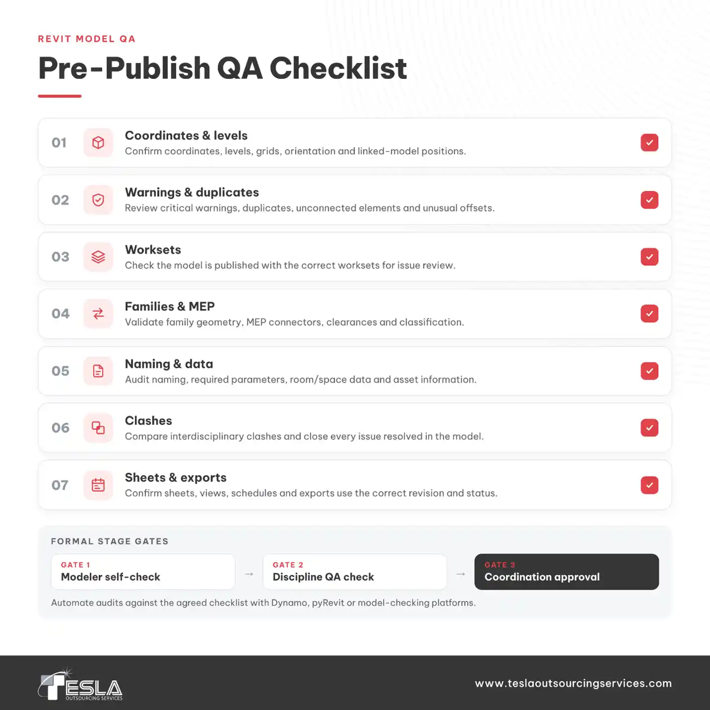
Pre-publish Revit QA checklist with formal stage gates.
Build Quality into the Modeling Process
If one mistakes a final clean-up of errors for quality, then all other teams’ work will go down the drain by the time the errors are found in a coordination meeting or even on site – well after the information has been used by the other teams.
As noted above, implementing a Reliability Review of the model to be handed over is enough to safeguard the many critical interests that model development satisfies. Preventing these simple errors means safeguarding more than the model’s integrity.
Where BIM data is clean enough to actually feed automation, the payoff is real. AI-assisted clash-detection tools are now achieving precision rates above 94%, and generative design tools can cut design time by up to 50%, but only on models with disciplined, well-structured family content to begin with.
Conclusion
Most costly Revit errors arise from decisions made early in the modeling process which, if planned out correctly, can be identified and corrected by the modeler before they affect drawings, quantities, fabrication, etc. By treating the coordinates, constraints, connectivity, families, warnings, and data in a Revit model with the same respect as one would for project-critical information, the model becomes more than just a design file to be used for coordinated delivery and informed decision-making.